02 · Scan to CAD

Turn scan data into usable engineering CAD.

We rebuild scan data into clean CAD geometry suitable for manufacturing, design validation and downstream engineering — giving you more than a mesh when the project needs an editable engineering model.
Input Physical part / scan data
Rebuild Parametric or surface-based
Output Production-ready CAD
PHYSICAL PART 3D SCAN CAD
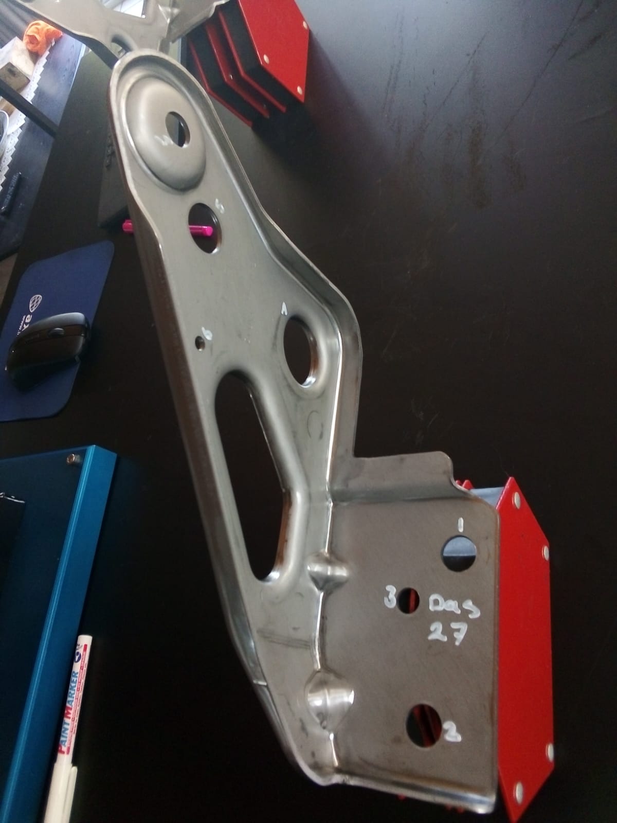
Original physical automotive bracket
01 · Source Physical Part
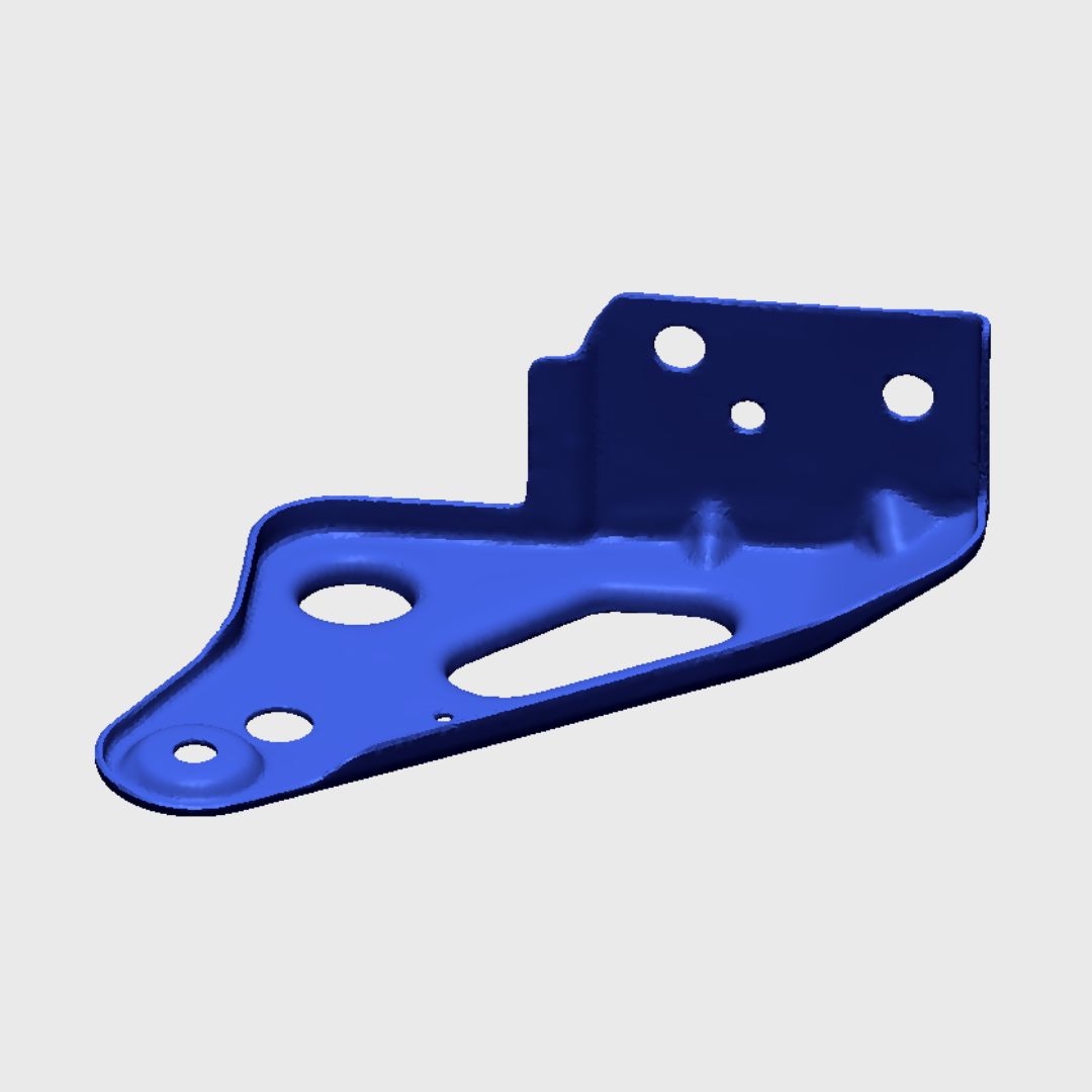
3D scan mesh of automotive bracket
02 · Capture 3D Scan
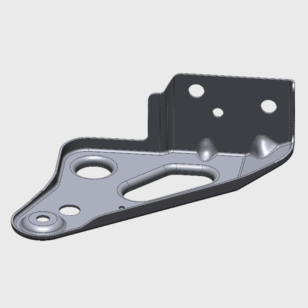
Reconstructed engineering CAD model
03 · Rebuild Engineering CAD
Where this service fits

A scan is geometry.
CAD makes it usable.

Scan-to-CAD bridges the gap between captured surface data and a model that can move into engineering, manufacturing or further design work.

Starting point

Scan / Mesh Data

Captured geometry accurately represents the physical part, but still needs reconstruction for downstream engineering use.

Result

Reconstructed CAD

Clean geometry rebuilt around the required engineering, manufacturing or design workflow.

Reconstruction options

CAD matched to the job.

Scan to CAD can range from a fast scan-following surface model through to a fully reconstructed engineering model. The right approach depends on how the CAD will be used afterwards.

01

Auto-Surfaced CAD

Convert captured scan geometry into CAD-compatible surfaces that closely follow the physical component.

  • Fastest reconstruction option
  • Closely follows scanned geometry
  • Ideal for reference and packaging
02

Hybrid CAD

Combine reconstructed engineering features with scan-derived surfaces where full parametric modelling is unnecessary.

  • Rebuilt critical features
  • Retains complex surface geometry
  • Balanced cost and usability
03

Full Parametric CAD

Reconstruct the component as clean engineering CAD for modification, manufacturing and future development.

  • Feature-led reconstruction
  • Editable engineering geometry
  • Production-focused output
Understanding the options

Different projects require different levels of reconstruction.

The amount of CAD reconstruction has a direct effect on the modelling time and project cost. We select the appropriate approach around the final use of the model rather than applying the same process to every scan.
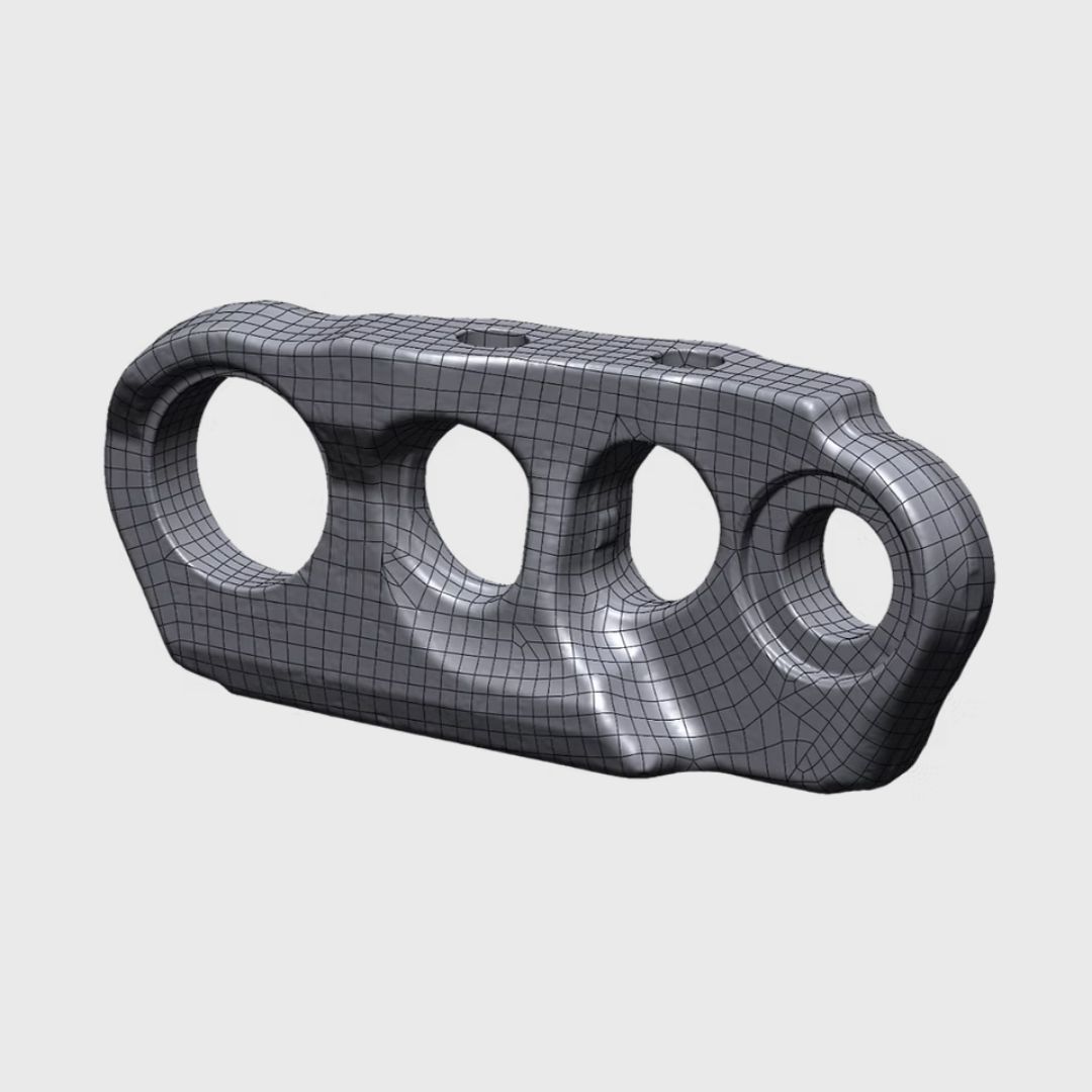
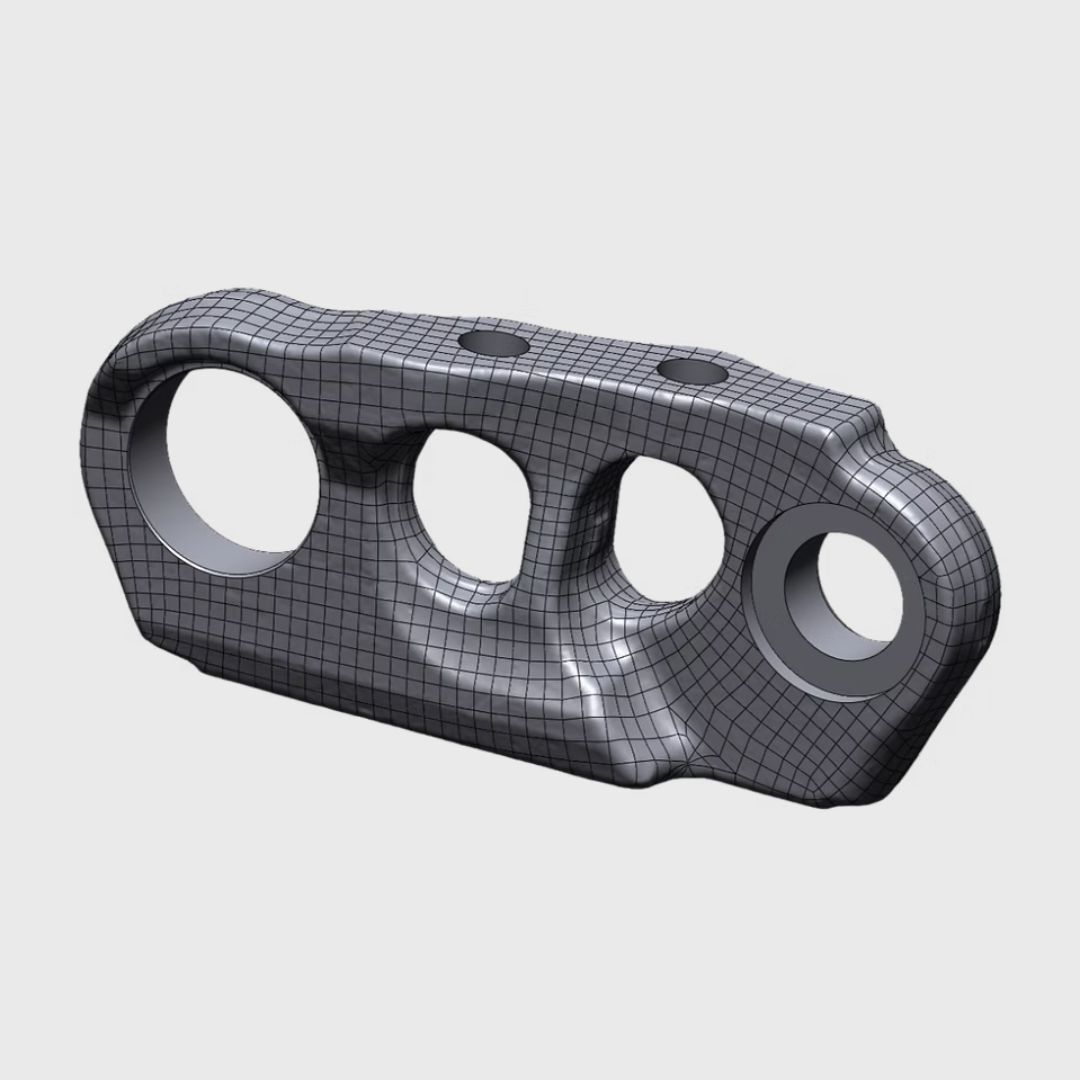
Auto surfaced Scan to CAD example
01 / AUTO-SURFACED CAD

When you need the scanned shape in CAD.

Auto-surfacing converts the captured mesh into a network of CAD-compatible surfaces. Rather than rebuilding the original engineering features, the model follows the physical shape recorded by the scanner.

Best suited to

Packaging studies, clearance checks, reference geometry, freeform components and designing new parts around an existing object.

  • Lower reconstruction effort
  • Maintains complex and organic shapes
  • Useful as external reference geometry
  • Limited feature-based editability
Hybrid Scan to CAD example
02 / HYBRID CAD

Rebuild what matters. Retain what doesn't need rebuilding.

Hybrid reconstruction combines conventional CAD geometry with scan-derived surfaces. Functional geometry such as mounting faces, bores, holes and interfaces can be rebuilt cleanly while complex surrounding surfaces remain scan-based.

Best suited to

Components that need accurate engineering interfaces but contain complex cast, moulded or freeform geometry that does not justify full parametric reconstruction.

  • Critical engineering geometry reconstructed
  • Complex surfaces preserved efficiently
  • Good balance between cost and CAD usability
  • Suitable for redesign and integration work
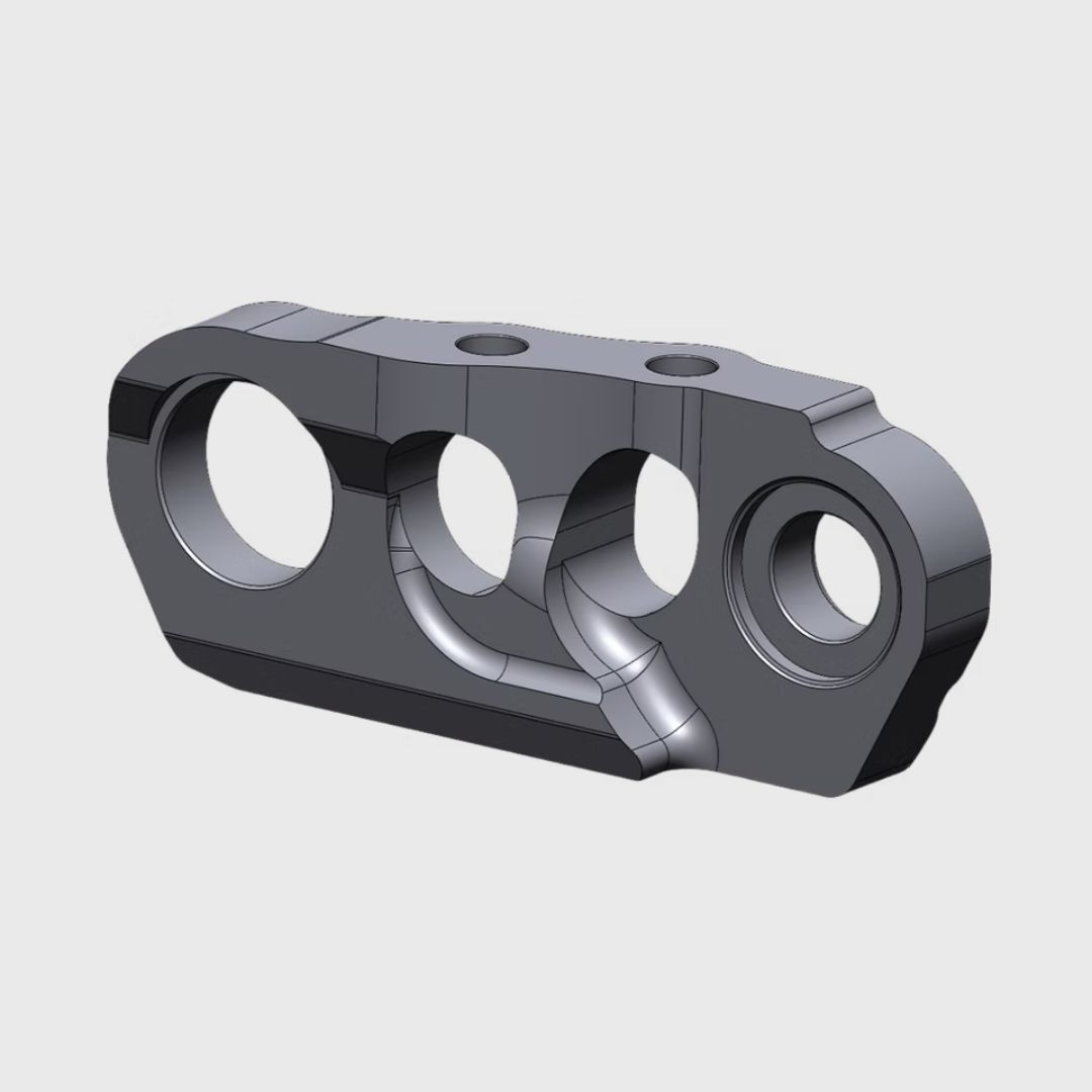
Full parametric Scan to CAD example
03 / FULL PARAMETRIC CAD

When the CAD becomes the new engineering master.

Full reconstruction interprets the scanned component and rebuilds it using clean engineering geometry. Features, dimensions and relationships are reconstructed so that the model can continue into redesign, manufacturing and future development.

Best suited to

Replacement components, legacy parts, manufacturing, product redevelopment and projects where the reconstructed model must remain useful beyond the scan itself.

  • Structured engineering reconstruction
  • Editable geometry where applicable
  • Can follow as-built or intended geometry
  • Suitable for manufacturing documentation
Reconstruction approach

As-built or design-intent CAD?

A scanned component may contain wear, distortion, manufacturing variation or previous modifications. The CAD reconstruction can either represent these real-world conditions or interpret what the original engineered component was intended to be.

Option A

As-Built CAD

Reproduce the relevant geometry as the component physically exists at the time of scanning.

Option B

Design-Intent CAD

Reconstruct the intended engineering geometry while correcting wear, distortion or irregularities where appropriate.

Additional deliverables.

The reconstructed CAD can continue into other engineering outputs depending on the project requirements.

Manufacturing Drawings

Production-focused 2D drawings can be generated from the reconstructed model where required.

Assembly Reconstruction

Multiple scanned components can be rebuilt and positioned together to reproduce an existing assembly.

Design Continuation

Use the reconstructed geometry as the basis for modifications, replacement parts or a new independent design project.

Typical Scan-to-CAD process

From captured data to reconstructed model.

01
Review

Review the available scan data, reference information and intended project outcome.

02
Clean

Prepare point-cloud or mesh data so the relevant geometry can be used as a reliable reconstruction reference.

03
Rebuild

Reconstruct the required geometry using a parametric or surface-based CAD approach.

04
Deliver

Provide the resulting CAD model, with drawings where included in the agreed project scope.

Common applications

Useful when the physical part is the reference.

Scan-to-CAD is particularly useful when original CAD is missing, the geometry has changed, or a physical object is the best source of truth.

LP
Legacy Parts

Recreate worn, damaged or obsolete components when original CAD or drawings are unavailable.

PD
Product Development

Turn prototypes and existing physical products into digital models for refinement and further development.

MF
Manufacturing

Develop production-focused models and documentation from physical reference geometry.

AR
Assemblies & Reference

Reconstruct parts or assemblies that are difficult to measure accurately with conventional tools.

What to send us

Start with the information you already have.

The project can begin from supplied scan data, or from a physical part that first needs to be captured through our 3D scanning service.

1
Scan or mesh data

Existing point-cloud or mesh files where available.

2
Photos and dimensions

Reference information that helps define the part and project context.

3
Required outcome

Tell us whether the model is intended for manufacturing, validation or further engineering.

Ready to start?

Have scan data or a part you need rebuilt?

Send photos, dimensions, scan data or a short project brief. We’ll recommend the most suitable CAD reconstruction approach for the required outcome.